Ohnuma Lab.
Reseach objectives


Our research interests are mainly related to power electronics and motor control technologies. Especially, modeling technologies are the biggest themes of our laboratory. We create mathematical models for motor controls.
Objective of our research is to improve performance of motor drive systems, such as extension of operating range in speed-torque plane. Efficiency improvement, and downsizing of motors and inverters are also important.
Interior Permanent Magnet Synchronous Motors
Recently, applications of IPMSMs (Interior Permanent Magnet Synchronous Motors) have been expanding, such as electric and hybrid vehicles, trains, pumps, home appliances, and so on. The IPMSMs feature compact and efficient, and also they have high power density.
Figure 1 shows a structure of IPMSM. Rotating part is called a rotor, and the permanent magnets are buried inside the rotor. The gray area shows the iron core. This kind of structure is called IPMSM. Stator is a fixed part of the motor. Three phase coils are placed in the stator. Three phase A.C. currents are supplied to the stator coils. Then, rotating magnetic field is generated by the current, and the permanent magnet inside the rotor is attracted by the magnetic field. This kind of torque is called magnetic torque. In addition, IPMSMs generate a reluctance torque, which is the magnetic attraction between the rotating magnetic field and the iron core. The IPMSMs are efficient and high torque density, because both torque components can be utilized at the same time. The control of the current vector is important to achieve it.
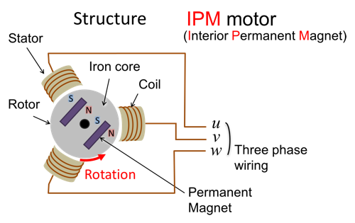
Figure 1. Structure of IPMSM
There are a lot of types in synchronous motors. Figure 2 represents the ratio of the torque components depending on the rotor structure. Permanent magnet motors are flexibly designed so as to satisfy the needs for each application. Recent special-designed machines are called application-specific motors.
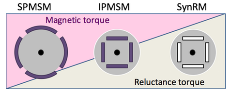
Figure 2. Types of Synchronous Motors
Application-specific motors need appropriate control techniques, because the torque characteristics are complicated and nonlinear. Figure 3 shows one example of torque characterisitcs of an IPMSM. As shown in the graph, the magnet torque has a peak at 90 degrees of current phase angle. On the other hand, the reluctance torque has a peak at 135 degrees. Therefore, the maximum point of the total torque appears between 90 and 135 degrees. Moreover, the maximum point depends on the current amplitude, that means the torque characteristics of the IPMSM are nonlinear to the current vector.
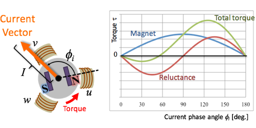
Figure 3. Torque Characteristics of a IPMSM
We use a current feedback controller to adjust the nonlinear torque properly. Figure 4 shows a typical control block of IPMSMs. We generally use a PI controller for the current control, and we have a coordinate transformation from d-q axes to three phase, and three phase to d-q axes. In the controller, we use a rotating reference frame, which is called d-q axes. The d-q axes is a coordinate system synchronizing with the rotor. The d-axis is defined to the direction of the magnetic pole of the permanent magnet in the rotor, and the q-axis is defined to the orthogonal direction of the d-axis. The rotating reference frame synchronizes with the rotor. Therefore, the current vector can be controlled as a D.C. current in the d-q coordinate system. In the d-q axes, motor toque is formulated by the equation (1). This concept makes it easier to design the controller.
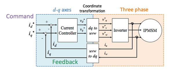
Figure 4. Current Control System for IPMSMs
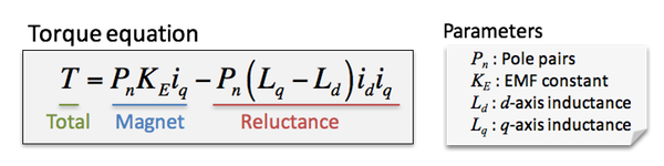 Equation (1)
Generally, design requirements for the controller are response, stability, and efficiency. Response means that when the command steps up, how fast the feedback follows the command. Second, stability means that after the change, how the feedback is settle at a certain value, or to keep under control against disturbances. Then, efficiency evaluates the ratio of output and input power.
Figure 5 shows a MTPA (Maximum Torque Per Ampere) control method, which is well known as a high-efficiency control. The MTPA control gives an optimum current phase to maximize torque for a current amplitude. As the current amplitude affects copper losses, the MTPA control minimizes the cupper losses. The d-axis current for the MTPA control is represented as equation (2). Figure 5 indicates the vector locus in the d-q axes.
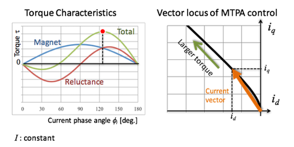
Figure 5. Maximum Torque Control
 Equation (2)
Maximum Torque Control Reference Frame (f-t axes)
Definition of "f-t axes"
We define a special coodinate system suitale for the controls of IPMSMs. Figure 6 shows the definition of the Maximum Torque Control Reference Frame, which is denoted as f-t axes.
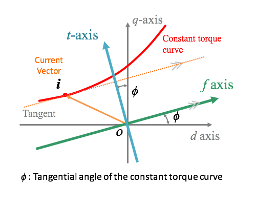
Figure 6. Definition of Maximum Torque Control Reference Frame
The f-t axes are based on a constant torque curve. The constant torque curve is a current vector locus where the motor torque is constant. The red line in Fig.6 indicates the constant torque curve in the d-q axes. The f-axis of the maximum torque control reference frame is defined to the direction parallel to the tangential line of the constant torque curves. The angle between d- and f-axes is derived from the torque equation as equation (3). The f-t axes are given by a rotational coodinate transformation from the d-q axes.
 Equation (3)
Characteristics of f-t axes
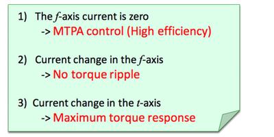
The f-t axes have three interesting characteristics in terms of the IPMSM controls. First, the MTPA control is realized simply by making the f-axis current component zero. As shown in figure 7, the operating point for the MTPA control gives a minimum distance from the origin to the constant torque curve in the d-q axes. In other words, a constant current circle comes in contact with the constant torque curve, and the tangential line is orthogonal to the radius vector. At this point, the current component in the f-axis is equal to zero. Second, current changes in the f-axis generate no torque ripple. If a signal current is injected in the f-axis, then the current vector changes along the constant torque curves. Therefore, the signal current in the f-axis does not generate torque ripple. We applied this current signal to estimate rotor position for position sensorless controls in our studies so far. Lastly, the t-axis gives maximum response for torque controls. If a current changes in a small amplitude without voltage saturation, then the t-axis current change directly gives a fastest torque response, because the t-axis points to the maximum inclination of torque contour lines. On the other hand, if the current change reaches large enough, a voltage saturation occurs in a high-speed region, and the fastest trajectory is given by a torque limiter. Even under the saturation condition, the f-t axes have the advantage of determining the phase angle for the maximum torque response. We develop various control techniques based on the f-t axes. Follow our research papers for the latest achievements.
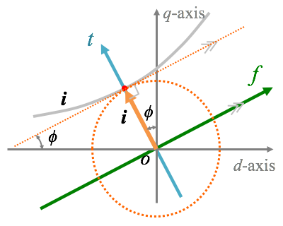
Figure 7. MTPA Control in the Maximum Torque Control Reference Frame
References
- *[1]
- Ryoh Saitoh, Yuki Makaino, Takumi Ohnuma: “Adaptive Signal Injection Method Combined with EEMF-based Position Sensorless Control of IPMSM Drives”, IEEJ Journal of Industry Applications, Volume 4, No.4, pp.454-459, July 2015
- *[2]
- Yuki Makaino, Tatsuya Iba, Takumi Ohnuma: “Maximum Torque Response Control based on Maximum Torque Control Frame”, IEEJ Journal of Industry Applications, Volume 3, No.3, pp.221-226, May 2014
- *[3]
- Takumi Ohnuma, Shinji Doki, Shigeru Okuma: “Signal Injection method without torque ripple based on maximum torque control frame”, IEEJ Transactions on Electrical and Electronic Engineering, Volume 8, Issue 1, pp.87-93, January 2013